 The
Train Collectors Society
The
Train Collectors Society
‘Any make, Any gauge, Any age’


![]()
A TCS Member's new Railway 'TOP SHED'
by Malcolm Pugh
Due to various circumstances, a TCS members' scenic OO layout built some 20 years ago into a 16 x 10 ft shed had to be dismantled.....after a short period he really missed having a working layout to be able to run some trains. It was at this point that I suggested that a small group could build a new layout in a larger shed which had become available. TCS members Andy and Elaine Hyleman, and Eric Large offered their services without too much persuasion! This new shed is just under 18 x 10 ft internally, with free standing large storage cupboards for rolling stock suitable for baseboards at waist height. The member wanted a four track design, with outer slow lines and two fast lines running through a station. A goods area, and a loco shed with turntable had to be included. At first, very ambitious designs were considered, but these were simplified down into a 18 x 6ft four track tail chaser, with rear storage loops, and a central front station with platforms on the slow lines. Crossovers are installed so that trains can move from fast to slow lines, and vice versa. A bay and 'reversing' platform are also to be provided, with a small goods area. This will enable trains to reverse direction. Spurs are to lead from each end to termini over the four former cheque book storage cupboards surplus to requirements from a bank, and a high level 'coarse' scale track to be built at the rear of the station to be able to run older Tri-ang stock. One thought is to add a central third rail to the high level, enabling Hornby Dublo and other similar vintage items to run. But the basic oval is the first phase, with the termini and high level to follow on later.
The layout is to be called 'Top Shed' named after Kings Cross. The 4 track running lines are also set out in LNER style, i.e. paired by direction.
In stock were two large sheets of 12 mm ply, and some long lengths of Dexion steel angle frame. Along with reclaimed fence posts from my old garden fence which when cut down formed the legs, a start was made on the woodwork in October 2006, and after two days we had a substantial structure. At the time comments were made like it was assembled from components from scrapheap challenge (or Junkyard Wars ). Some new 2 x 1 timber was purchased to form the cross supports for the ply sheet.
A further visit was made to tidy up the woodwork, reinforce the ply sheeting and add leg bracing. Total build time 10 man days. Then came Christmas, when the team had other commitments, so progress stopped, but this gave me time to accumulate certain items that were not to hand, mainly second hand but in excellent condition Peco points in large radius straight and curved units. In the meantime, a large 2 track 'test track' some 16 x 4 feet had been made by the owner, enabling trains to be run. This track was made on separate boards, and is suitable for TCS meetings, as each section breaks down to 6 feet.
January 2007 and track laying started. Peco code 100 nickel silver track has been used, much of it reclaimed from the previous layout, but some as new lengths were to hand. Cork tiles have been used as a surface on top of the ply, this makes adding the point rodding and wired fairly easy, also it quietens the running noise slightly. Eric had drawn the plan out using AutoCAD ( see the trackplan with dimensions in mm ), and had printed off full size the trackplan on A4 paper, which we were able to place on the baseboards and imagine how it would look before any rails had been laid. Approval was given, so after one weekend 2 tracks were operational, then after another couple of visits, all 4 main circuits worked. Each circuit has it's own DC controller, and there are multiple power feeds for each circuit. Power switching utilises the isolating aspect of Peco points, supplemented by a couple of micro switches operated by the point tie bars. Peco point motors have been fitted above the board, this simplifies installation, and makes maintenance much easier. They will be concealed by scenery later. either behind backscenes, or under suitably placed structures. It is intended to motorise all the points, as work progresses the more remote points are being converted first. Changing the layout to DCC would be fairly easy should this be required in the future. it's just the large number of motive power units that would need to have decoders fitted. And some of the older type motors have a high current consumption compared to more recent types, the decoders for these power hogs would be much more expensive than the £10 devices which now are acceptable. Perhaps as an option, one portion of the layout could be switchable to DCC. Track laying so far has taken another 10 man days, giving a cumulative total of 20 man days. Really it should be person days, as some of the construction has been done by Elaine...and you can't tell where it is as the quality of her workmanship matches the men!
The next stage is to construct a control panel, this will be on castors and have lengthy trailing cables enabling operation either from the central well, or from either end.
To be
continued....but don't hold your breath!
![]()
Yes, the woodgraft was successful, and the patient will make a full recovery.
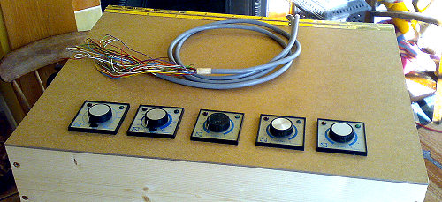
We spent Saturday afternoon building the control panel base and sides from
..... gasp shock horror ..... NEW wood. When we came to attach the control
panel surface using the piano hinge, we needed a thin strip of wood, a lucky
find in the scrap wood store finished the job, maintaining the tradition of
component recycling where possible.
Sunday saw the original power feeds to the tag strips removed, and the new controllers wired and tested. We got everything right, apart from one controller works back to front, even though we thought we had put it in temporarily and already reversed it. Unfortunately, we didn't have all the controllers of the same type, some are centre off, some are fully left for off, making operation difficult at times. However, once the Member, we are building it with, has made known his preference as to which type, then replacements can be obtained.
The multi cables for the track and point feeds are in, the next stage is to slightly modify the track plan to enable better return terminus-main line- terminus operation ..... an oversight in the original design. The rear point solenoid studs and position repeater LEDs can be wired, then it will be considerably easier to operate the rear loops.
Then some modification to the yard wiring, enabling independent operation when not set for the main lines.
Malcolm
PS For
those not in the 'know', Ellis was a bedside cabinet on castors, why he/she
was called Ellis, only the Membership Secs. know.
And from the Membership Secs.
And Ellis? Well he was actually an Ikea desk, whose name was Ellis in their catalogue.......and knowing an (ex) colleague called Ellis somehow the name got remembered!
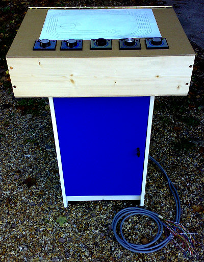
Ellis re-born !!
To be continued.......................
![]()
‘Any make, Any gauge, Any age’
TCS©2009